domingo, 26 de agosto de 2018

Worm Gear Calculation

No one that is involved in design wants to deal with Worm gears. Just the engineers or designers that are familiar with this type of applications have no problems to understand the development, working conditions, manufacturing and design of a worm gear set.
In my case, it took me a long period of time to have an idea about the minor details of this mechanical element, and I am just able now to define them geometrically, calculate the forces and evaluate the proper assembly and understand some cases of failures.
I have read some articles and gear handbooks to verify the informatoin given in this application for Android, wich is going to be available in three of four weeks.

Here you have some links to useful information:

KHK gears
Autodesk Basic Information
Research gate Worm Gears PDF

I will add more information of worm gears while I am progressing with the application.

Worm Input motion:

Here we have the worm wheel in motion with the worm. Input and output together.


Now the final animation is ready. Time to work in the app.


It took me more time than I wanted, but the app is now available in Google Play.
The application will help you to design a worm gear according to the reccomendations found in different articles and books.
You may need to know the transmission ratio of your gearset, as well as the center distance between worm and wormgear.
After filling those two variables, the worm should be defined with a set of parameters that are neccesary to calculate the whole gearset. The app will give you some indications to fill them.

The following images explain the way to work with this new application:


The application is available in Google Play:


What have I learned during the application development and the usage of this type of mechanical ellements...
First of all, this type of gear set has the difficulties of a typical gear set design with the difficulties of the a bevel gear transmission.
The capacity of provide a huge reduction in a very small space would drive engineers to think in this transmission as a solution instead of using, maybe a planetary system. But, consider the following facts:

- Worm gear manufacturing is difficult and should be done by specific manufacturing suppliers that could provide the quality you require for your application.

- Worm wheel, may not be as difficult to machine as the worm and it will not need a quality grade as tight as the worm also, because it will tend to wear and accomodate the worm geometry to the tooth surface and part of the geometric deviations will dissapear, but it will need some work to think the way you want to attach this worm wheel (in general a piece that would be serviceable) to the ouput shaft.

- The location of the gear contact has, in worm gear design, three possible linear deviations. Compared to a typical spur gear set, the worm and worm wheel could move in X, Y and Z direction, Probably the center distance is the one that in general can not be adjusted by shims, but the axial location of the worm as well as the axial direction of the worm wheel can be adjusted slightly.
Doing that, you can reduce the transmission error and adjust the backlash of your system.

- Lubrication, Lubrication and Lubrication. It is essential to provide good lubrication to the gear mesh because the relative motion between gears is almost sliding. Therefore, oil type and oil lubrication method should be designed carefully.

Here you have some links to useful information I found about worm, and worm wheels:


martes, 19 de diciembre de 2017

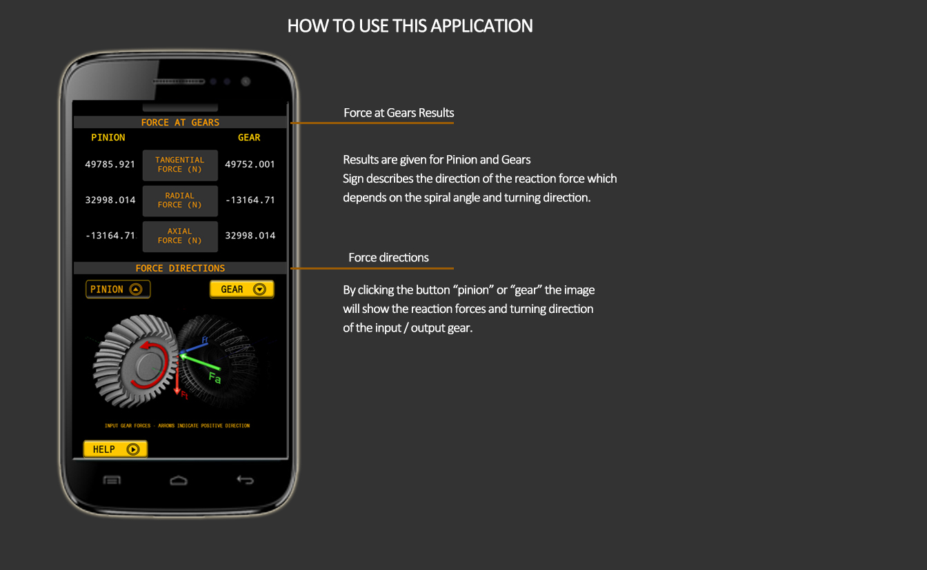
Spiral Bevel Gear Forces

This application has been created to help designers with the reaction forces generated in the spiral bevel gear set. Due to the spiral angle and turning direction the forces are not, let's say, directly obtained as it happens with straight bevel gears.
As a reference, this web can help to understand better the forces in different gear types, including spiral bevel gears:


martes, 20 de diciembre de 2016

Politica de Privacidad

POLÍTICA DE PRIVACIDAD 
La presente Política de Privacidad establece los términos en que DAV.Trocoide usa y protege la información que es proporcionada por sus usuarios al momento de utilizar su sitio web o aplicaciones
Ninguna de nuestras aplicaciones recoge, solicita o trata datos personales de ningun tipo.
Esta pagina WEB no recoge, solicita o trata datos personales de ningun tipo.
DAV.Trocoide no te pedira en ningun caso datos personales, correo electronico o cualquier tipo de informacion personal.
PRIVACY POLICY
This Privacy Policy establishes the terms in which DAV.Trocoide uses and protects the information that is provided by its users when using its website or applications.
None of our applications collects, requests or processes personal data of any kind.
This WEB page does not collect, request or process personal data of any kind.
DAV.Trocoide will not in any case ask you for personal data, email or any type of personal information

sábado, 23 de julio de 2016

Shaft - Hub Press Fit Calculator

When I started to work in things related with mechanisms, materials, engineering details, transmissions...etc I was struck by the torque and resistance capacity of these type of press fit joints. 
Nobody told me, by this time, how well should be controlled the dimensions of the parts that create the joint. Even small tolerances expand considerably the difference between min and max torque capacity.
I hope the list of suggestions I am writing here help you to design your joint:
  • If your joint rotates and you can add a key in your joint, just do it, It is a safety device that will help you to sleep better.
  • Double check the expansion of the external part, the hub. Only in the case your surrounding parts are too close to the hub.
  • Provide generous chamfer at the hub and shaft entries.In general a 20 degree angle is enough. During the assembly, try to avoid an edge contact between parts, so look at the interference sequence and verify that chamfer ends do not coincide by the time you start to press. Sometimes a difference in the chamfer angle helps.
  • Tolerance ranges capable and reliable for a standard grinding are around ±0.013, Eventhough you can use a tight values like ±0.008 but probably your cpk would be far away from 1.33 unless you pay so much for the parts.
  • Take care with thinner parts. On shafts, the inner diemater can end as an oval. If you press fit so much a bearing cup, the rolling ellements could find areas with less clearance than others and that would generate a speed reduction in your rolling elements, sliding, heat and infant failures. In the other hand, a thin hub, will copy so well the shaft geometry that any size imperfection will end at the outside of the hub. Also the torque capacity will be very poor and depending on the material, the elastic curve of the hub can easily be overpassed and finally yields to a permament deformation.
  • Use if possible a retainer compound,
  • If possible, use the same material for hub and for shaft. If not possible, at least both would have the same elasticity module. In case using a different material have a look at the part with the lowest module, this one will limit the capacity and the geometry of the joint.
  • To obtain better results and to avoid excessive wear during the assembly, due to the friction between surfaces a hub preheat or a shaft temperature reduction is needed in some cases. Also that effect will help the assembly process o reduce the force needed to join the parts. Caution must be taken to avoid preheat at temperatures that could temper the parts and reduce its surface hardness. In general, I do not accept prehteats that exceeds 180 ºC.


domingo, 21 de febrero de 2016

Gear Design Application and Gear Stress Calculation


Video Tutorial Available:


Description of each parameter / variable:

Module: Indicates the tooth size and is the number of mm pitch circle diameter(p.c.d.) per tooth. Many parameters are related to this value. The module will determine the gear tooth strength, and in fact, it will define the overall gear size.


Teeth Number: Teeth number of pinion and gear relation define the gear transmission, or gear ratio.Together with the module defines the pitch diameter of each gear. It also has a great influence in the contact ratio of the gear pair. Check the minimum Teeth number needed for a specific gear pair to avoid interference. Thee are many references in the web. 

Addemdum Factor:
By default, a value of 1.25 is recommended. When playing with this value, you will notice that tip diameter will change.


jueves, 17 de diciembre de 2015

Gear Profile Tolerances

I think that one of the best ways to understand a subject is trying to build something that uses somehow materials that are part of this subject. I mean, if you want to know something about the wind, you can start building your own weather-vane, and probably you would need to read about this matter before starting to make anything until you gain the confidence to put your weather-vane at the top of the roof.
That's what have happened with this application. I am not a super gear expert but I have to deal with them, I have to decide if something has to be scrapped or not, and understand quality deviations over the tooth surface to move forward with the parts, test them, rework them (not always possible).
As many others technicians I had many doubts about how to interpret the information coming from quality, from the measurements of the gear profile, so I decided to read, and collect enough information to be sure that next time I have to review a gear report, I would have the chance to see it with a different perspective.
So, here you have some notes, links and a application created for android to define the deviation values of the profile (surface) of a gear tooth.

First of all, deviation calculations are based on the standard DIN 3691, which is similar to the ISO1328 or AGMA ISO 1328.

I will try to describe the three most important measurements (or type of measurement) that are always reported in a gear inspection:

 Profile Deviations:

If you hear the word "profile" of a gear, you should relate it to the arc that goes from the bottom of the tooth to the top of it, basically up to the tip or outside diameter of the gear.
In general, deviations in the profile, are only measured at the 92% of the active length, and it is called "profile evaluation range".
As it is defined by the ISO 1328, "Profile deviation is the amount by which an actual profile deviates from the design profile. It is in the transverse plane and normal to the involute profile."

The image describe how the profile is obtained from the roll angle of the gear tooth.


Image taken from :http://www.gearsolutions.com/article/detail/5565/an-elementary-guide-to-gear-inspection


Type of Profile Errors:

Three important types of errors are related to profile, Profile Form Deviation, Profile Slope deviation and Total profile deviation.

Profile Form Deviation (ffa):
Distance between two involutes of the actual base circle, that enclose the actual involute profile within the profile inspection range
Can also be defined as the divergence of the measured profile from a best fit line or curve.

Profile Slope Deviation (fHa):
Distance between two nominal profiles that intersect the average profile at start and end points of the profile range or Profile slope deviation is the amount of deviation from a nominal involute profile over the evaluation range.

Total Profile Deviation: (Fa):
Is the total amount of profile error, including slope and form errors or the distance between two nominal profiles enclosed within the profile test range.


Images taken from:http://www.geartechnology.com/issues/1194x/smith.pdf

Helix deviations:

AGMA’s current inspection handbook defines “helix deviation” (formerly tooth alignment variation and lead variation) as the difference between the measured helices to the design helices. In practice an appropriate measuring machine aligns the measuring probe on the test gear at the pitch circle diameter and the “lead” is traced and recorded graphically, with a correct unmodified helix being represented as a straight line on the chart. Helix measurement is used to determine correct face contact between mating gears. Incorrect helix will create uneven loading and noise.
The ISO 1328 explained in the following terms:
" Helix deviation is the amount, measured in the direction of the transverse base tangent, by which an actual helix deviates from he design helix ".
Image taken from :http://www.gearsolutions.com/article/detail/5565/an-elementary-guide-to-gear-inspection

Type of helix errors:

Helix Form Deviation (ffb):
Distance between two helical lines that enclose the actual lead within the lead inspection range. Helix form deviation is the divergence from a best fit curve along the helix

Helix Slope Deviation (fHb):
Helix slope deviation is the amount of deviation from a nominal helix over the evaluation range. Distance (in transverse plane) between two nominal leads that intersect the average lead (helix) at start and end points of the lead inspection range.

Total Helix Deviation (Fb):
Distance between the two nominal leads enclosed within the lead inspection range.The total amount of error including angle and form errors.


This picture is quite helpful because it gives you an idea bout the way the tooth is measured and what is the meaning of the traces showed in the right side.

Pitch Deviations:
The notation pitch, should make you think about tooth location, and the effect that this type of deviations would have into the gear motion and torque transferring. It is related to, backlash, contact ratio variation...
It is looking at the location of a gear tooth with respect to the others, as well as the global location between all gear teeth. Measures, the difference between the actual position of the tooth and the "should be here" position.
The application calculate the values of the pitch error (fu), the single pitch deviation (fp) and total pitch deviation (Fp).

Types of pitch deviations:

Single pitch deviation (fp):
It is the difference between two adjacent teeth index values (+,-) or the algebraic difference between the actual pitch and the corresponding theoretical pitch in the transverse plane, defined on a circle concentric with the gear axis at approximately mid-depth of the tooth.

Pitch Error (fu):
It is the difference between adjacent pitches.The difference between actual dimensions of two successive right or left flank transverse pitches.

Total cumulative pitch deviation (Fp):
Maximum cumulative pitch deviation of any sector of the corresponding flanks of a gear. It is represented by the total amplitude of the cumulative pitch deviation curve.


Pitch deviations


Gear index and pitch definitions.

Transmission error deviations (tangential composite deviations):
In this case, those deviations are related to the gear motion. You need to look at the gear in touch with a master gear and how the center of the gear changes when it revolves one complete turn. That will affect load transferring, and bearing cycle load reactions.
The application gives two different values:

Two flank working deviation( f´´i):
Maximum difference between the effective and theoretical circumferential displacements at the reference circle of the gear under inspection, when meshing with a master gear, testted product gear being turned through one complete revolution.


Single flank working deviation (f´i): 
Value of the tangential composite deviation over a displacement of one pitch. It is a true tangential measurement and is indicative of the functional characteristics of the gear.The non uniform motion is called "transmission error"


As a reference, here you have also a table with the quality grades comparison between DIN and AGMA standards:


Finally, the link to the Application. You can find it at Google Play.

 Gear Profile Tolerances

App Images:


Links to the different documents used to create this entry:


miércoles, 25 de noviembre de 2015

Epicyclic Gears

This Android App is designed to perform an initial calculation of a simple epicyclic arrangement with a sun, ring, planets and carrier.
Define the motion parameters, teeth number of the different elements and the speed and torque to obtain different results as:
  • Total ratio of the system.
  • Relative motion to the carrier.
  • Geometry verification.
  • Absolute Speed of each element.
  • Cycle counting, Tooth Contact per minute of each gear
  • Factorization value of Sun and Ring Gear
  • Torque results of each element.
Different animations are included within the app, just click at the image at the right side of the motion selection.
Also, the definition of "factorization" is described in this video (click to the link)

 App Images:


A link to a youtube video created for each motion definition is available when clicking over the gear image.

Three different types of motion were created:

Planetary:


Solar :


Star:


Many links and lectures are recommendable, I have found interesting for basic and intermediate study the following links and Standards: