Mostrando entradas con la etiqueta Aluminum. Mostrar todas las entradas

domingo, 26 de agosto de 2018

Worm Gear Calculation

No one that is involved in design wants to deal with Worm gears. Just the engineers or designers that are familiar with this type of applications have no problems to understand the development, working conditions, manufacturing and design of a worm gear set.
In my case, it took me a long period of time to have an idea about the minor details of this mechanical element, and I am just able now to define them geometrically, calculate the forces and evaluate the proper assembly and understand some cases of failures.
I have read some articles and gear handbooks to verify the informatoin given in this application for Android, wich is going to be available in three of four weeks.

Here you have some links to useful information:

KHK gears
Autodesk Basic Information
Research gate Worm Gears PDF

I will add more information of worm gears while I am progressing with the application.

Worm Input motion:

Here we have the worm wheel in motion with the worm. Input and output together.


Now the final animation is ready. Time to work in the app.


It took me more time than I wanted, but the app is now available in Google Play.
The application will help you to design a worm gear according to the reccomendations found in different articles and books.
You may need to know the transmission ratio of your gearset, as well as the center distance between worm and wormgear.
After filling those two variables, the worm should be defined with a set of parameters that are neccesary to calculate the whole gearset. The app will give you some indications to fill them.

The following images explain the way to work with this new application:


The application is available in Google Play:


What have I learned during the application development and the usage of this type of mechanical ellements...
First of all, this type of gear set has the difficulties of a typical gear set design with the difficulties of the a bevel gear transmission.
The capacity of provide a huge reduction in a very small space would drive engineers to think in this transmission as a solution instead of using, maybe a planetary system. But, consider the following facts:

- Worm gear manufacturing is difficult and should be done by specific manufacturing suppliers that could provide the quality you require for your application.

- Worm wheel, may not be as difficult to machine as the worm and it will not need a quality grade as tight as the worm also, because it will tend to wear and accomodate the worm geometry to the tooth surface and part of the geometric deviations will dissapear, but it will need some work to think the way you want to attach this worm wheel (in general a piece that would be serviceable) to the ouput shaft.

- The location of the gear contact has, in worm gear design, three possible linear deviations. Compared to a typical spur gear set, the worm and worm wheel could move in X, Y and Z direction, Probably the center distance is the one that in general can not be adjusted by shims, but the axial location of the worm as well as the axial direction of the worm wheel can be adjusted slightly.
Doing that, you can reduce the transmission error and adjust the backlash of your system.

- Lubrication, Lubrication and Lubrication. It is essential to provide good lubrication to the gear mesh because the relative motion between gears is almost sliding. Therefore, oil type and oil lubrication method should be designed carefully.

Here you have some links to useful information I found about worm, and worm wheels:


lunes, 16 de febrero de 2015

Fastener Torque Calculation

Developed for designers and engineers that look for more information about the fastener than only the torque value.

This tool uses the concept of "Utilization Factor", that varies from 0.5 to 0.8. This factor is linked to the type of work the fastener is going to do in the joint. From just a quick clamp, no structural, no risk joint to a design where the fastener perfomance is critical.

Here are some screenshots of the application:

 
  Fastener Torque Calculation


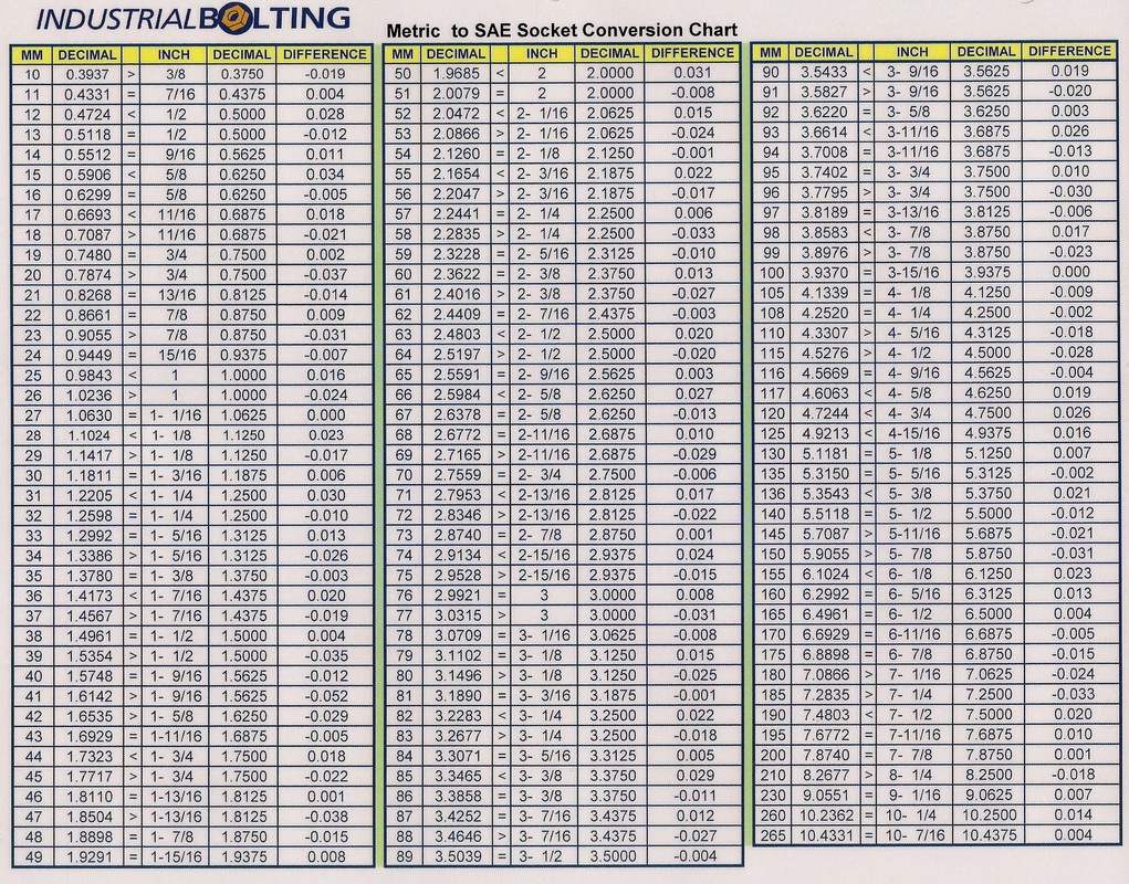
    Additional information about joints and fasteners:
   Lessons learned:
  • Provide enough clearance for the wrench tools to access to the head of the bolt.
  • Be sure that bolt can be assembled and dismounted, specially attention with long bolts that may be replaced without tier down all the transmission,
  • Try to standarize all bolt types and sizes in the gearbox, specially in areas where the bolt is working in the same way. (housing calmping bolts for example)
  • Do not mix same bolt sizes with different grades in one gearbox position.
  • In castings, be sure that bolt head is not contacting an angled surface. Try to clean up always the casting surface, specially in aluminum castings.
  • In aluminum, use roll form threads.
  • When specifying the hole dimensions, leave at least 3 times the pitch size of gap between the tap drill depth and the thread depth. One way to specify this type of geometry can be done in this way: 
    • Speficy the tap drill Max depth and specify the thread Min depth.
  • A whaser under the bolt head can promote a better pressure and contact distribution. 
  • Find the right location tolerances when defining the joint holes. Keep in mind always the rule of Clearance = Tolerance. An acceptable position value for threaded holes might be between 0.6 - 0.8. The MMC of the bolt is always its Outside diameter. From those values you may find the hole through diameter and its tolerance.
  • If your calculations consider the bolt to be dry and without oil, make sure that you are receiveing this from your supplier.
  • When the shank diameter of a bolt is less than the thread diameter thus allowing a radiused thread runout which reduces stress concentration - beneficial in fatigue applications.
  • Distance between bolts to clamp the gearbox housings toghether should be around at 6.5  - 7 times the bolt diameter. (Example, M12 bolt diameter, distance between bolts should be around 78 mm and 84 mm)
  • Avoid curved geometry between bolts in gearbox housings. Always think on designing for the min distace between bolts.
  • If you suspect fatigue, a rule of thumb is to calculate the number of cycles a ferrous metal part has been exposed to before it failed:
    • Failure at less than 10,000,000 cycles:  suspect fatigue.
    • Failure at over 100,000,000 cycles: fatigue is not likely.
    • It only takes 3600 rpm motor only 46 hours to produce 10,000,000 cycles.
    • A 75 Rpm mixer shaft coupling bolt failing after 2 ½ years has over 100,000,000 cycles.
    • From Fatigue Failure in Bolted Joint
  • When joining materials with strengths lower than that of the bolt strength, a washer must be used to avoid bearing failure at the bolt/nut-material interface. In this case a washer should be used under both the nut and head of the bolt.
  • The larger the washer diameter the thicker and stiffer the washer should be. It is also apparent that the strength of the washer must be at least equal to the strength of the bolt.